Monday, May 9, 2016

Navigating with a Map and GPS

Navigation with a Map and GPS

Introduction:

The goal of this activity was to use a navigational map that was created a few weeks ago to navigate a course through the forest to different way-points as assigned by the instructor. The only tools we had to use where the navigational maps, one of these is seen in figure 1, and an Etrex GPS as seen in figure 2. The points were given on a sheet of paper and we had to travel from one point to the next collecting way-points all the while collecting a track log of where we traveled so a path from one point to another could be seen.
 Figure 1: The navigation map used for the project.
Figure 2: An Etrex GPS was used to gather simple points and a travel track.

Methods:

The first step of the afternoon was to plot out the assigned points onto the 11x17 printout of the navigation map. This enabled the group to visualize where, in reference to the other points assigned, each point was. The most direct path to each point was then figured out with a goal of zig-zagging through the woods as little as possible. The GPS was set to collect points in Wisconsin UTM Meters and the project began. As we walked a track collected points along our path so that an overall travel route would be visible then when the exact coordinated of the points assigned were reached a way-point was added.


Figure 3: Point #1: Point one was collected as a light drizzle began to fall. There were large storm clouds on the horizon highlighting the fact that any type of weather can occur in the field and it is important to be prepared.
Figure 3: Point #2: At each data point a geotagged photo was taken as the way point was collected as proof of out finding the location in case there was a GPS technical error.

Figure 4: Point #3: Armed with a map print out, a GPS, and coordinated for assigned points, navigation
Figure 5: Point #4: Finding the exact point required several double checks and turning in circles to arrive at the exact location.

Figure 6: Point #5: The woods we navigated through were thick with the invasive species buck thorn and required a lot of changing of course to get by dead falls and ravines.

Results:

The final product of the track is visible in figure 7 as a map simplified to show the track traveled. The 50 meter grid lines were useful when determining what lines to take to the next point. The grids were used to determine rough distances between points to decide which points to collect first. Our best determined route was to go from point 2 to 4 then across to 5 and up to 1 then finally down to 3 for the very last point.
My group used different methods  to get from each point to the next, most of the time a simple walking in the right direction until coordinates were narrowed down was used. When going from point 4 to 5 I held the GPS and wanted to try to use the pace count to go straight through the woods in the right direction to arrive at the point,Point 5 was 183 of my paces away from point 4. The use of this pace practice is visible on the map as a heading was taken and that direction was followed until 183 paces were reached and distance on the GPS was checked. Mild correction was needed but overall it was accurate.


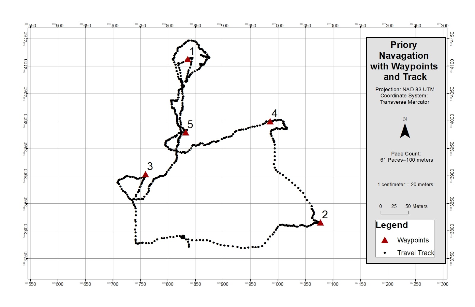
Figure 7: This simple display easily shows the track taken to and from points while on the navigation route as well as the way-points.

Discussion:

The navigation map worked surprisingly well and with each point that was collected we felt more and more confident. The hardest part was keeping the numbers in the correct order when comparing desired location to current location on the GPS, often times the numbers got jumbled and the coordinate sheet had to be referenced several times. My favorite part of this lab was absolutely seeing how accurate pace and a heading can be when going from point 4 to 5, though several scratches were gathered on that route as an attempt to maintain a straight line it was neat to use a different very basic navigation method.
Clearly, as seen on the map, some points were much easier to find, in some cases we found ourselves wandering about in circles only to arrive back at a point we had been at minutes before as seen in the case of way-point #1. Not every point was as easy to gather as the first point but overall we proved that we could use basic navigation relying on coordinates and a compass on the GPS as well as a pace count to go from point to point with relatively few errors and problems. After this lab I know better how to navigate with a map and feel confident in relying on a map I myself made to travel on an assigned route.
.


Monday, May 2, 2016

Pix 4D Demo

Processing UAS Data in Pix 4D

Introduction:

The purpose of the activity for this week is to become familiar with running a file from a UAS in Pix 4D to create a 3D map. The program uses the geocoded points connected to the image files as a "geotag" to create a point cloud. The images are combined into one image and the z value is added to that image to push it up or down depending on the collected elevation.

In order to do this the pixels of each image have to be laid on top of one another perfectly to create the combined image. The connection points the images use to link up are called keypoints. It takes two keypoints to create one 3D point. There must be at least two keypoints or there is no way to create a 3D image. If the are of interest is rather bland or featureless there is a need for even more keypoints as it is more difficult to connect the images when they are so similar. Often times it will help to know whether or not sufficient points were gathered for coverage(figure 1). To test this a process called "rapid check" can be used. This is a tool that sacrifices accuracy for speed and quickly runs a low quality check on the data to ensure proper coverage.
For larger projects it is likely that multiple flights will need to be done to cover the study area. Though the data is stored in a separate file, Pix4D can still run analysis on multiple flights at once. However the pilot has to be sure of a few things, the conditions have to be similar to ensure data integrity and there must be sufficient overlap to connect the keypoints.
Pix4D also has the ability to process oblique images(figure2). These are images that are taken at 90 degrees or more from the surface of the Earth. A traditional aerial image we tend to think of is taken from 0 degrees, straight down at the Earth. Oblique images are taken of things like towers and buildings. If no ground control points are used, if there is nothing tying the data to a specific place on the ground, there is still a possibility of an output. Though they are highly recommended they are not needed to create a result with no scale, orientation, or any positional information
At the end of running a project a quality report is displayed. This appears after each step is run as a way to check in on the progress of a project, sort of like a print statement in PyScripter. 

Figure 1: This figure displays how much overlap between taken points is needed between two flights in order to link them,

Figure 2: This diagram displays what it means to collect data from images taken at different angles to the ground. 


Methods:

In this exercise the simple application of running the program to create a 3D map was done. To do this a folder of images is added to the program as a "new project". Some specifications can be set at this point and then the initial analysis of the images is run. This is the section where the keypoints within the rasters are connected together and their geotags link them to the location they were taken on the globe, giving them spatial reference. 
In the case of this project, 80 photographers were used and went through initial processing. This process took well over an hour. Once done however, the program had created several links between images allowing for a 3D image to be eventually created, these connection can be seen in figure 3. The connected images combine to form one image with 3D capability (figure 3).

Figure 3: The geotags on each image are used to connect images to each other, the more lines connecting points, the more reliable the connection between images is. This graphic shows that the images in this project have very high connectivity.


Results:

After the program is run, several things can be done with the data and resulting images. One of the first images created with the data, displayed in the quality check is figure 4, displaying the elevation of the points as well as a compiled image creating one picture of the track area that was constructed of several images from the drone.
Figure 4: A result of the initial processing showing the compiled image on the left and the raised features on the right.


Figure 5: The combined DEM of the images gathered from the UAS with a spatial reference.

Conclusion:

The goal of this activity was to become familiar with using images from a UAS in Pix4D as an introduction to what can be done with this kind of data. One of the features that can be done is a 3D fly over where an animation is made of a view going over and around the area of interest. This file is a .gif that displays what the image looks like from what the UAS saw as it collected points. One of the issues I encountered with this activity was exporting that .gif as the default was to an excel or .csv file format which did not help. What I needed was a short video clip exported as a video file not a text file. I also had trouble with the aspect of calulating volume of an object. I was able to trace the shed shown along the track on the bottom right of the image but could not calculated meters cubed. There are more things that can be done with this data and hopefully more will be done as I am able to work some of the programs within Pix4D such as the fly over and calculating the volume of an object in the AOI. As this is an introduction I hope to get a little more experience and be able to do some of the more analytical aspects of this program. I have gathered a brief understanding but certainly need more experience working with this program to become efficient with it.